Imprinting
In this post I’ll describe an alternative to a vignette post processing effect. I haven’t seen this technique described before so I’m calling it an imprint for lack of a better term.
Note I’m using assets from Unity’s Adventure Sample Game for demonstration purposes.
All the gameplay screenshots in this post are using Adventure Sample Game assets, not from the unannounced Double Loop game.
Background
Many games need to focus the player’s attention on specific content on screen. In my first blog post I used a vignette post processing effect darken the game world a short distance away from the player’s character when the player was low on health. This works really well in situations where there’s a single area to focus on, but it becomes less effective at directing the player the larger the vignette becomes (since the player won’t know exactly where in the larger area to look).
For example, if you want to highlight both the player and a powerup they should get, it may require a full-screen vignette. In a local co-op game you might have additional player characters that need their own highlights. While it’s certainly possible to extend Unity’s vignette shader to support multiple locations on-screen that should have vignettes, if you want to take into account the position, rotation, and scale of each object it’s going to start to require quite a few shader properties that need to be updated each frame.
Another challenge with using a vignette effect is trying to make the effect maintain a consistent look across different aspect ratios. If you have UI elements that anchor themselves to screen edges, you’d have to make sure that the vignette settings accounted for that possibility. On the flip side, art that’s in the world rather than in the UI will not act like that - its position will not be affected by aspect ratio unless the camera field of view changes.
Brainstorming
It would be a lot more convenient if the post processing effect just depended on the transforms & shapes of the affected objects. They should be able to move around on screen and change shape without having to manually update the vignette about their new transform or bounds. One way to do that would be to add a shader pass to the materials used by objects we want to highlight and have them draw into a render texture instead of the camera render target.
Another option would be to add an additional material to the mesh renderer component if it’s not convenient or possible to modify the shader used by individual objects. While it might be reasonable to do that for one or two shader types, it could start to get tedious to support characters, environment art, VFX, and UI. That might not be possible if you can’t customize the mesh renderer components to do so.
Depending on your situation, shader replacement might also be an option if you want all characters with specific shader tags to get the effect. However, if you have multiple objects on screen that should get the effect and they all use the shader, there isn’t a great way to override properties for a subset of renderers since code applying replacement shaders doesn’t provide individualized access. It’s also not possible to rely on properties that weren’t assigned to the original material.
Ultimately the solution I ended up settling on (and there are probably other options) was to attach a MonoBehaviour to all game objects that should get an imprint and then make it the responsibility of the post processing effect to draw those objects into a render texture used as an input texture on a full screen post processing effect. It relies on the CommandBuffer passed via the context parameter of the post processing effect to manage both the render texture and the drawing requests. The sample grayscale effect in the documentation already demonstrates a very simple use of the command buffer - to draw a full screen effect using the previously rendered content combined with a material.
Organization
Since I have a whole blog post dedicated to configuring post processing and another blog post to creating other types of effects, please read through them if you’re unsure about how to install and setup Unity’s post processing package for your cameras & scenes.
This new effect will start with the same basic setup that the Grayscale sample uses, namely:
ImprintEffectwhich is based on the post processing package settings type which is used to save/load data specified in the Post Processing ProfileImprintRendererwhich is based on the post processing package renderer type to handle applying the effect to the output of the previous post processing effects (or the camera output if it’s the only effect)Imprint/Showwhich is based on the post processing package shader to transform the post processing stack input (or the camera output) with the imprints and produce a final composite
In addition, there are two more pieces specific to the Imprint technique:
ImprintBehaviour, a MonoBehaviour attached to any object that should not be affected by screen darkeningImprint/Make, another shader being used to draw each object with anImprintBehaviouron it into a render texture passed to theImprint/Showshader to determine where to apply the effect
ImprintEffect
The implementation is minimal - it just has a blending factor to determine the intensity of the darkness applied to any areas of the screen that aren’t being highlighted.
1
2
3
4
5
6
7
8
9
10
11
12
13
14
15
16
17
18
using System;
using UnityEngine;
using UnityEngine.Rendering.PostProcessing;

namespace Imprint.Runtime.Effects
{
    [Serializable]
    [PostProcess(renderer: typeof(ImprintRenderer),
        eventType: PostProcessEvent.AfterStack,
        menuItem: "Imprint")]
    public class ImprintEffect : PostProcessEffectSettings
    {
        #region Fields
        [Range(min: 0f, max: 1f), Tooltip(tooltip: "Filter intensity.")]
        public FloatParameter Blend = new FloatParameter { value = 1.0f };
        #endregion
    }
}
ImprintBehaviour
The implementation is minimal - it adds itself to a global HashSet when the component is enabled and removes it when disabled. It expects to have a Renderer assigned to determine the transform and bounds of the object. If your objects have multiple Renderer components you can either customize this class and the ImprintRenderer to expect that or use one ImprintBehaviour per Renderer. The static HashSet will be iterated by the ImprintRenderer to determine which objects need an imprint.
1
2
3
4
5
6
7
8
9
10
11
12
13
14
15
16
17
18
19
20
21
22
23
24
using System.Collections.Generic;
using UnityEngine;

namespace Imprint.Runtime.Effects
{
    public class ImprintBehaviour : MonoBehaviour
    {
        #region Properties
        public static IEnumerable<ImprintBehaviour> Instances => sBehaviours;
        public Renderer Renderer => _Renderer;
        #endregion

        #region Fields
        private static readonly HashSet<ImprintBehaviour> sBehaviours =
            new HashSet<ImprintBehaviour>();

        [SerializeField] private Renderer _Renderer;
        #endregion

        protected virtual void OnEnable () => sBehaviours.Add(item: this);

        protected virtual void OnDisable () => sBehaviours.Remove(item: this);
    }
}
ImprintRenderer
The implementation is a little more involved than the Grayscale example renderer since it needs to obtain an additional temporary screen-sized render texture and then draw each imprint into it using the Imprint/Make shader. Once that is finished, the Imprint/Show shader is used to composite the previous post processing results (or camera output) with the temporary imprint render texture to darken areas without imprints.
I used the Sphere primitive mesh to draw imprints using DrawMesh but you could use whatever mesh you like or use DrawRenderer instead to draw the actual renderer assigned to the ImprintBehaviour if you don’t want to include any of the surroundings.
Note that it’s important that the temporary render texture is cleared to black before we draw into it since the Imprint/Show shader expects black to mean not imprinted and white to mean imprinted.
1
2
3
4
5
6
7
8
9
10
11
12
13
14
15
16
17
18
19
20
21
22
23
24
25
26
27
28
29
30
31
32
33
34
35
36
37
38
39
40
41
42
43
44
45
46
47
48
49
50
51
52
53
54
55
56
57
58
59
60
61
62
63
64
65
66
67
68
69
70
71
72
73
74
75
76
77
78
79
80
81
82
using UnityEngine;
using UnityEngine.Rendering.PostProcessing;

namespace Imprint.Runtime.Effects
{
    public class ImprintRenderer : PostProcessEffectRenderer<ImprintEffect>
    {
        #region Fields
        private static int sRenderTextureID;

        private Material _Material;
        private Mesh _Mesh;
        #endregion

        public override void Init()
        {
            base.Init();

            sRenderTextureID = Shader.PropertyToID(name: "_ImprintTex");

            _Material = new Material(shader: Shader.Find(name: "Imprint/Make"));
            var gameObject = GameObject.CreatePrimitive(type: PrimitiveType.Sphere);
            _Mesh = gameObject.GetComponent<MeshFilter>().sharedMesh;
            Object.DestroyImmediate(obj: gameObject);
        }

        public override void Release()
        {
            base.Release();

            Object.DestroyImmediate(obj: _Material);
        }

        public override void Render(PostProcessRenderContext context)
        {
            var sheet = context.propertySheets.Get(shader: Shader.Find(name: "Imprint/Show"));
            sheet.properties.SetFloat(name: "_Blend", value: settings.Blend);

            // Draw Imprint renderers into a temporary render texture (using the Imprint/Make shader)
            // so that the Show shader knows where they all are.
            context.command.BeginSample(name: "Imprint");
            context.GetScreenSpaceTemporaryRT(cmd: context.command, nameID: sRenderTextureID);
            context.command.SetRenderTarget(rt: sRenderTextureID);
            context.command.ClearRenderTarget(
                clearDepth: false,
                clearColor: true,
                backgroundColor: Color.black);

            // Note that for simplicity this doesn't do any culling or instancing.
            foreach (ImprintBehaviour imprintBehaviour in ImprintBehaviour.Instances)
            {
                if (imprintBehaviour.Renderer == null)
                {
                    continue;
                }

                // Create a uniformly scaled shape using the max bounds along any axis to ensure
                // it keeps a consistent size no matter how the character rotates.
                Bounds bounds = imprintBehaviour.Renderer.bounds;
                float width = Mathf.Max(a: bounds.size.x, b: bounds.size.y);
                width = Mathf.Max(a: width, b: bounds.size.z);
                Vector3 scale = Vector3.one * width;
                Matrix4x4 matrix = Matrix4x4.TRS(
                    pos: bounds.center,
                    q: imprintBehaviour.Renderer.transform.rotation,
                    s: scale);
                context.command.DrawMesh(mesh: _Mesh, matrix: matrix, material: _Material);
            }

            // Now that all the imprints have been made into the temporary render texture, perform
            // post processing using the Show shader.
            context.command.SetGlobalTexture(nameID: sRenderTextureID, value: sRenderTextureID);
            context.command.BlitFullscreenTriangle(source: context.source,
                destination: context.destination,
                propertySheet: sheet,
                pass: 0);

            context.command.ReleaseTemporaryRT(nameID: sRenderTextureID);
            context.command.EndSample(name: "Imprint");
        }
    }
}
Imprint/Make shader
This implementation is also very minimal - it just draws white into the texture wherever there is geometry from an imprint.
1
2
3
4
5
6
7
8
9
10
11
12
13
14
15
16
17
18
19
20
21
22
23
24
25
26
27
28
29
30
31
32
33
34
35
36
37
38
39
40
41
42
43
44
Shader "Imprint/Make" {
    HLSLINCLUDE
        #include "Packages/com.unity.postprocessing/PostProcessing/Shaders/StdLib.hlsl"

        struct Attributes {
            float4 positionOS : POSITION;
        };

        struct Varyings {
            float4 positionCS : SV_POSITION;
        };

        Varyings Vert (Attributes input) {
            Varyings output = (Varyings)0;

            float4 positionWS = mul(unity_ObjectToWorld, input.positionOS);
            output.positionCS = mul(unity_MatrixVP, positionWS);

            return output;
        }

        half4 Frag (Varyings input) : SV_Target {
            return half4(1, 1, 1, 1);
        }
    ENDHLSL

    Category {
        Tags { "IgnoreProjectors" = "True" }

        LOD 100
        ZWrite Off

        SubShader {
            Tags { "RenderType" = "Opaque" }

            Pass {
                HLSLPROGRAM
                    #pragma vertex Vert
                    #pragma fragment Frag
                ENDHLSL
            }
        }
    }
}
Imprint/Show shader
The implementation is also very simple - it reads an additional texture to determine the blending between full color camera output and darkened areas that are not highlighted. Note that I didn’t bother to add a property to specify the imprint texture since it’s just fed by the shader effect but you could do that if you want to debug it in isolation. Expect that the _Blend property value will get overwritten by ImprintRenderer too.
1
2
3
4
5
6
7
8
9
10
11
12
13
14
15
16
17
18
19
20
21
22
23
24
25
26
27
28
29
30
31
32
33
34
35
36
37
38
39
Shader "Imprint/Show"
{
    Properties
    {
        _Blend ("Filter Intensity", Range(0, 1)) = 1.0
    }

    HLSLINCLUDE
        #include "Packages/com.unity.postprocessing/PostProcessing/Shaders/StdLib.hlsl"

        TEXTURE2D_SAMPLER2D(_MainTex, sampler_MainTex);
        float4 _MainTex_ST;
        TEXTURE2D_SAMPLER2D(_ImprintTex, sampler_ImprintTex);
        float4 _ImprintTex_ST;

        half _Blend;

        half4 Frag (VaryingsDefault input) : SV_Target {
            float imprint = SAMPLE_TEXTURE2D(_ImprintTex, sampler_ImprintTex, input.texcoord).x;
            float4 color = SAMPLE_TEXTURE2D(_MainTex, sampler_MainTex, input.texcoord);
            color.rgb = lerp(color.rgb, color.rgb * imprint.xxx, _Blend.xxx);
            color.rgb *= color.a;
            return color;
        }
    ENDHLSL

    SubShader {
        Cull Off
        ZWrite Off
        ZTest Always

        Pass {
            HLSLPROGRAM
                #pragma vertex VertDefault
                #pragma fragment Frag
            ENDHLSL
        }
    }
}
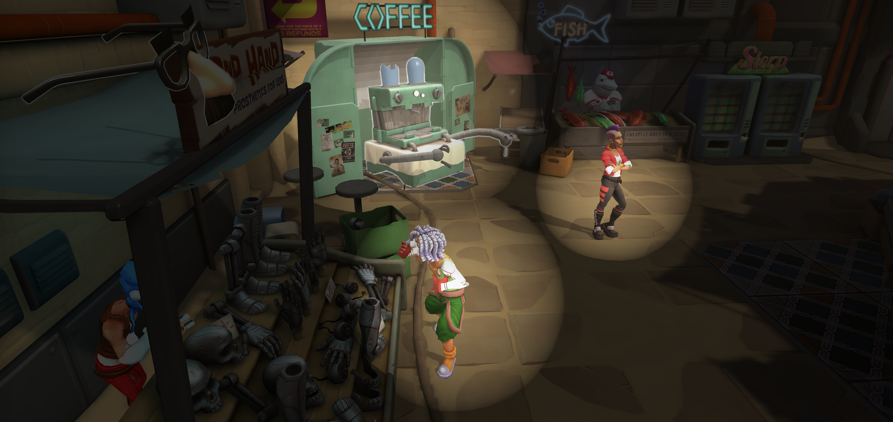
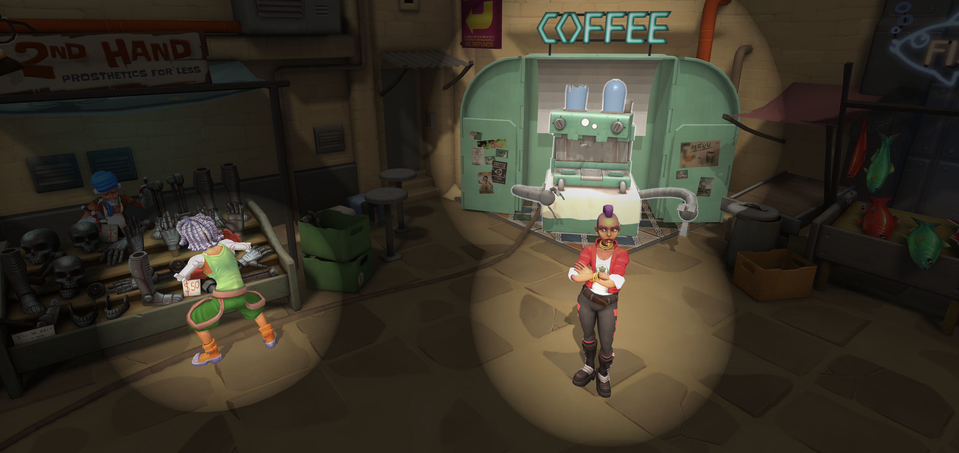
First Impressions

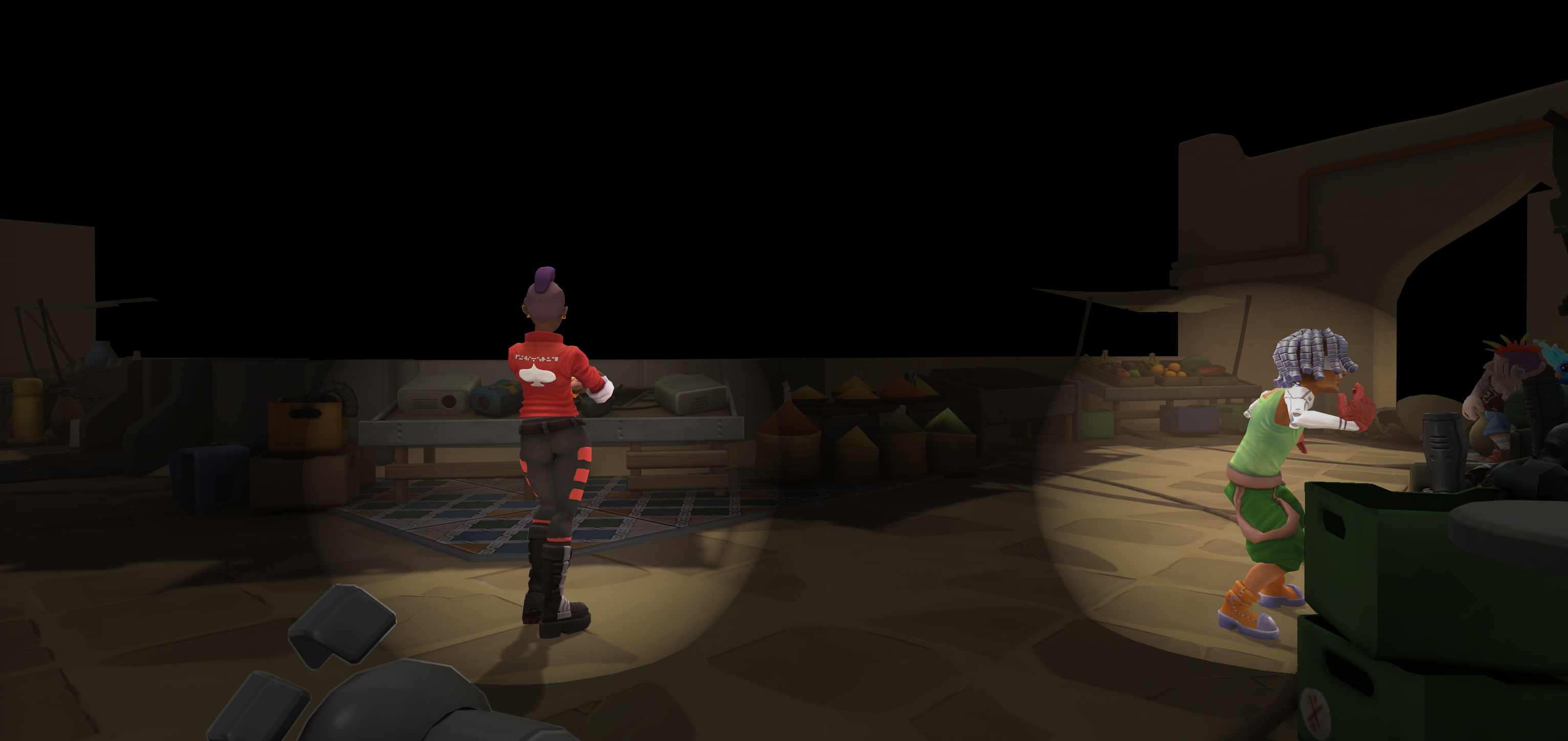
(Left) The Market demo scene from the Unity Adventure Sample game with multiple imprints active.
(Right) A debug view of the same scene showing the areas the imprints are active.
Let’s take a look at the output in a sample scene. It gets the job done nicely; the screen is darkened except wherever renderers set to leave an imprint are positioned. However, I think it’s worth trying to make the impression edges softer like you’d get in a vignette. A standard vignette effect can do this easily when it’s done in screen space since you can calculate where the edges of the screen are in screen space. However, although the Imprint/Show shader also works in screen space, it doesn’t know where the edges of each imprint are. While we could try a shader-based multi-sample edge detection technique like is used for anti-aliasing, that only performs well for a small number of samples. If we want imprints to have a very soft edge it would have to sample many pixels to find the edges.
Another option might be to have the Imprint/Make shader encode the imprints into the temporary render texture as a signed distance field. If you haven’t heard of the technique before, this would mean that each pixel in the texture would contain the distance to the nearest shape. This is what TextMesh Pro uses for efficient resizable font rendering. When sampling the texture, you’d know based on the sign of the value whether you were inside or outside of the shape and based on the magnitude how far away you are from the edge of the shape. This technique would also allow you to draw any sort of screen-aligned signed distance shapes without relying on a real mesh. However, since it only works on primitive shapes that you specifically code in the shader, I set it aside.
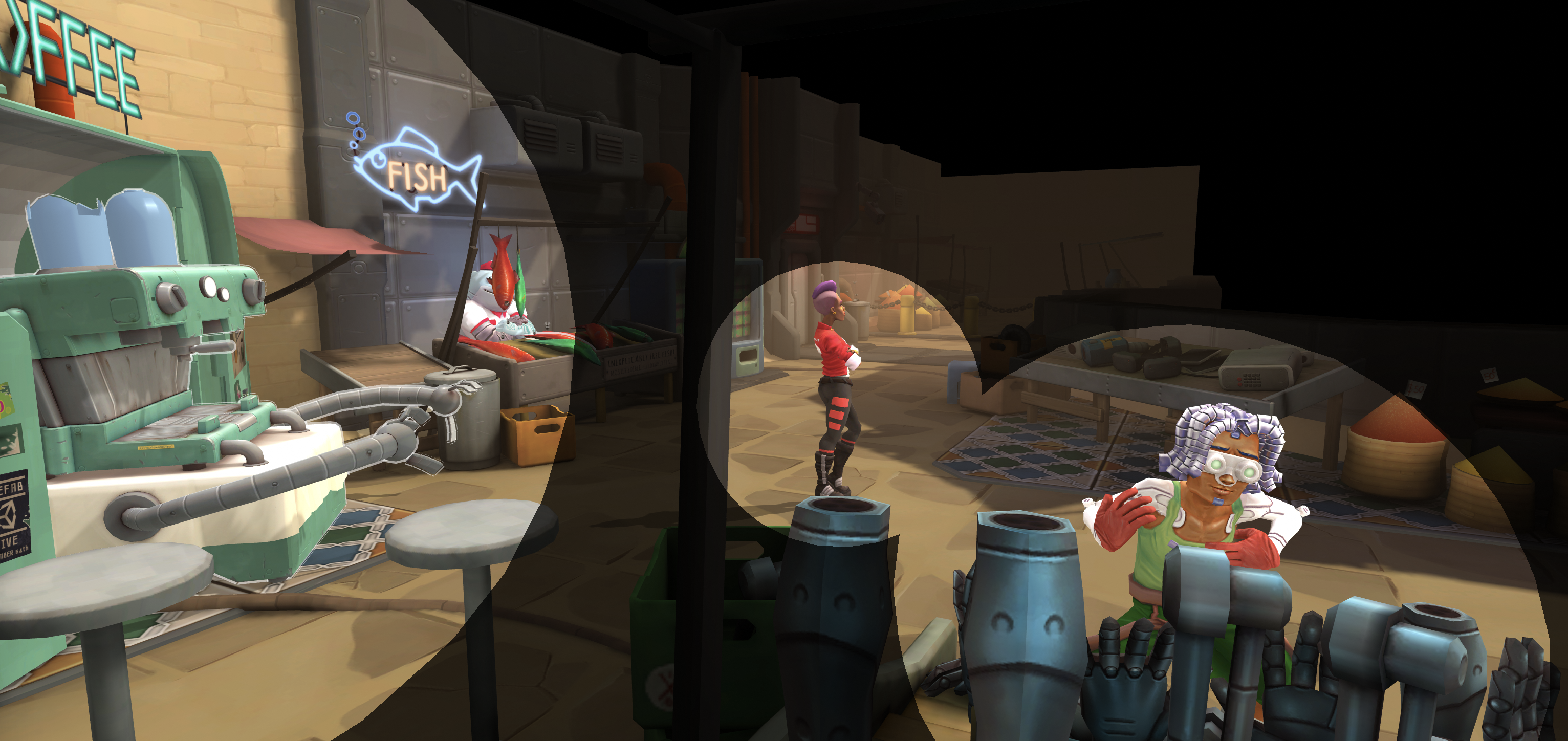
The option I ended up going with was to use a fresnel effect where the parts of the shape facing orthogonal to the camera become darker (most fresnel effects make these brighter). There’s a lot of great literature out there already about fresnel effects in Unity so I’m not going to dwell on its usage here and just present the altered shader. As you might expect, it relies on a per-vertex normal (which thankfully is set in the primitive meshes) along with the world space camera position. Some additional calculations occur in the vertex shader to arrive at the fresnel value which is then passed to the fragment shader and used as the output color (since it was just white before there’s no point in multiplying it by 1). If you want to tweak the fresnel strength, then you can expose a property on the shader to override the 0.75 passed to the pow function and hook it up to a property exposed by the ImprintEffect settings.
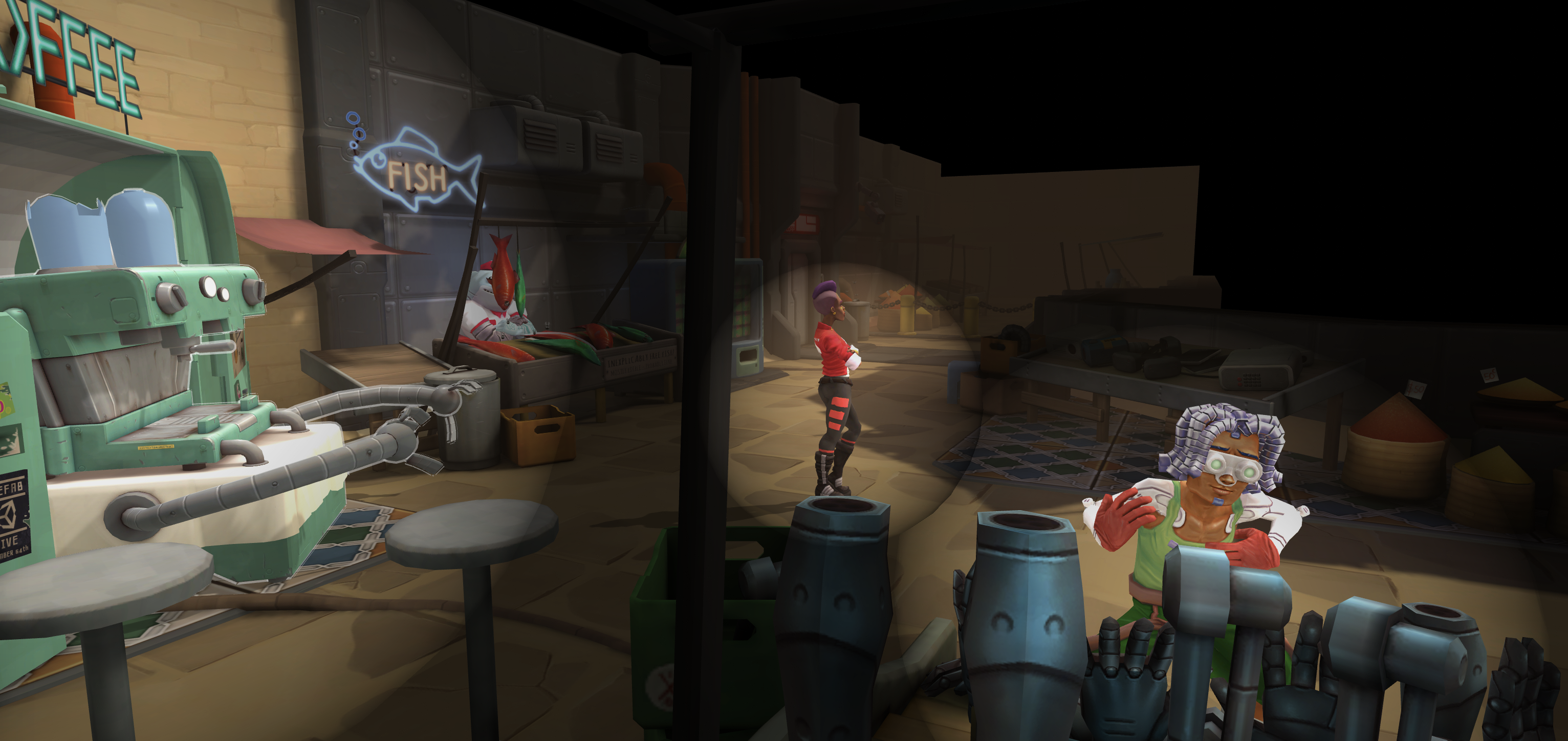
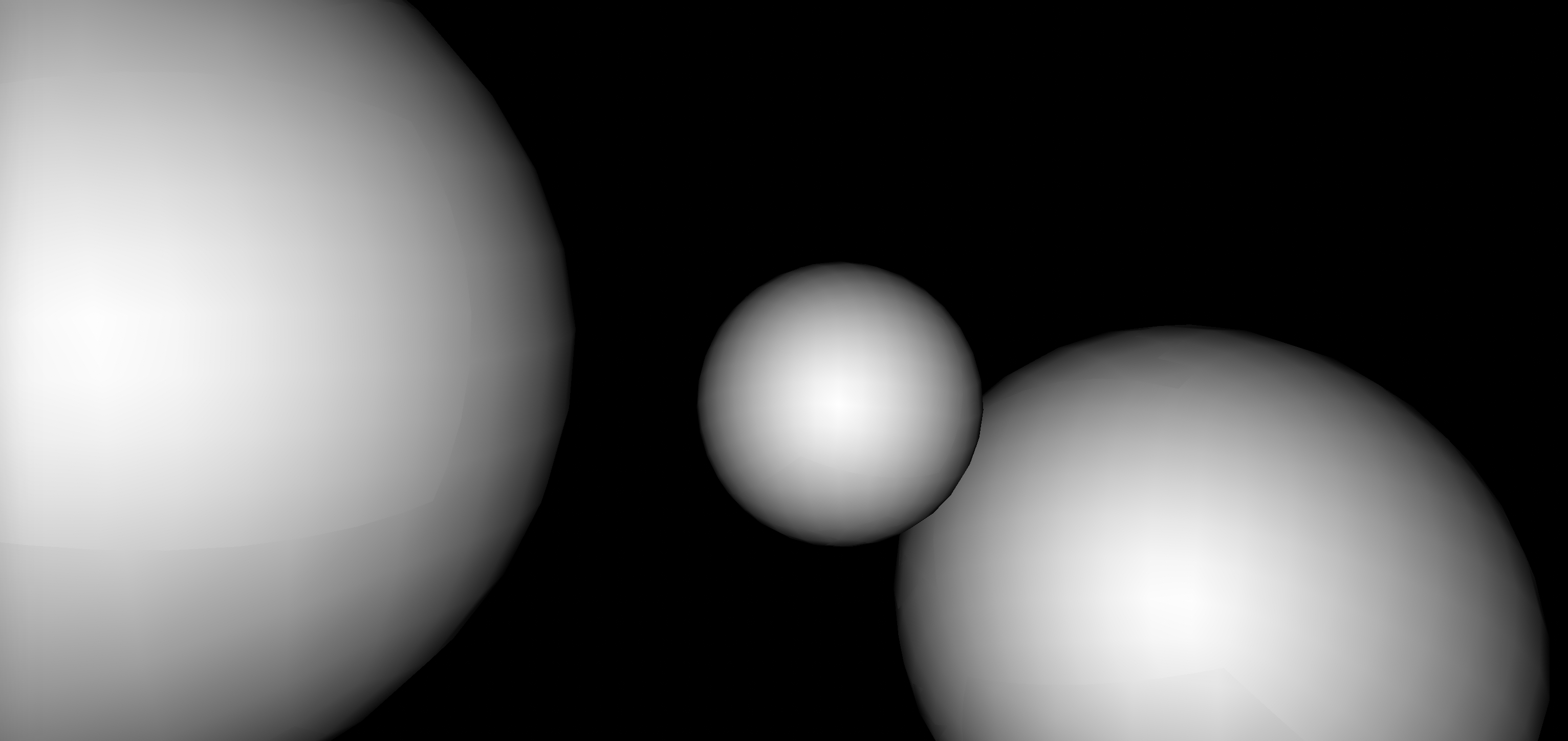
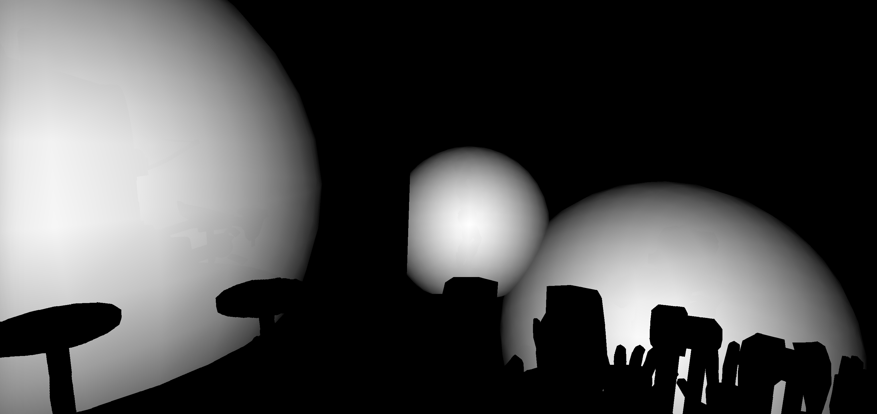
(Left) The Market demo scene with a fresnel darkening the edges of each shape.
(Right) A debug view of the same scene showing the affected areas and fresnel attenuation.
1
2
3
4
5
6
7
8
9
10
11
12
13
14
15
16
17
18
19
20
21
22
23
24
25
26
27
28
29
30
31
32
33
34
35
36
37
38
39
40
41
42
43
44
45
46
47
48
49
50
51
52
Shader "Imprint/Make" {
    HLSLINCLUDE
        #include "Packages/com.unity.postprocessing/PostProcessing/Shaders/StdLib.hlsl"

        struct Attributes {
            float4 positionOS : POSITION;
            float3 normalOS : NORMAL;
        };

        struct Varyings {
            float4 positionCS : SV_POSITION;
            float fresnel : TEXCOORD0;
        };

        Varyings Vert (Attributes input) {
            Varyings output = (Varyings)0;

            float4 positionWS = mul(unity_ObjectToWorld, input.positionOS);
            output.positionCS = mul(unity_MatrixVP, positionWS);

            // Calculate fresnel
            // In this case the fresnel is inverted so that edges are darkened.
            float3 eyeNormalWS = normalize(positionWS.xyz - _WorldSpaceCameraPos.xyz);
            half3 vertNormalWS = normalize(mul(unity_ObjectToWorld, input.normalOS));
            output.fresnel = 1. - pow(1. + dot(eyeNormalWS, vertNormalWS), 0.75);

            return output;
        }

        half4 Frag (Varyings input) : SV_Target {
            return input.fresnel;
        }
    ENDHLSL

    Category {
        Tags { "IgnoreProjectors" = "True" }

        LOD 100
        ZWrite Off

        SubShader {
            Tags { "RenderType" = "Opaque" }

            Pass {
                HLSLPROGRAM
                    #pragma vertex Vert
                    #pragma fragment Frag
                ENDHLSL
            }
        }
    }
}
Blending Together
This ends up providing a soft edge to the shape and should work well for any meshes that have vertex normals configured as expected. This works great for a single imprint, but unfortunately the effect probably won’t look right if you have multiple overlapping imprints - you can end up with darker overlapping outlines due to the fresnel, but the impact depends on the draw order. Currently ImprintRenderer draws objects in the order that the HashSet enumerator provides them which is effectively arbitrary. Unfortunately sorting them won’t help in all situations - especially partial overlaps. Thankfully we can use blending in the shader to achieve this. While traditional blending techniques use Blend SrcAlpha OneMinusSrcAlpha, instead of adding the source and destination values together, we really want the max of the source and destination. Fortunately, we can set BlendOp Max and Blend One One to take the maximum of the full source and destination values.


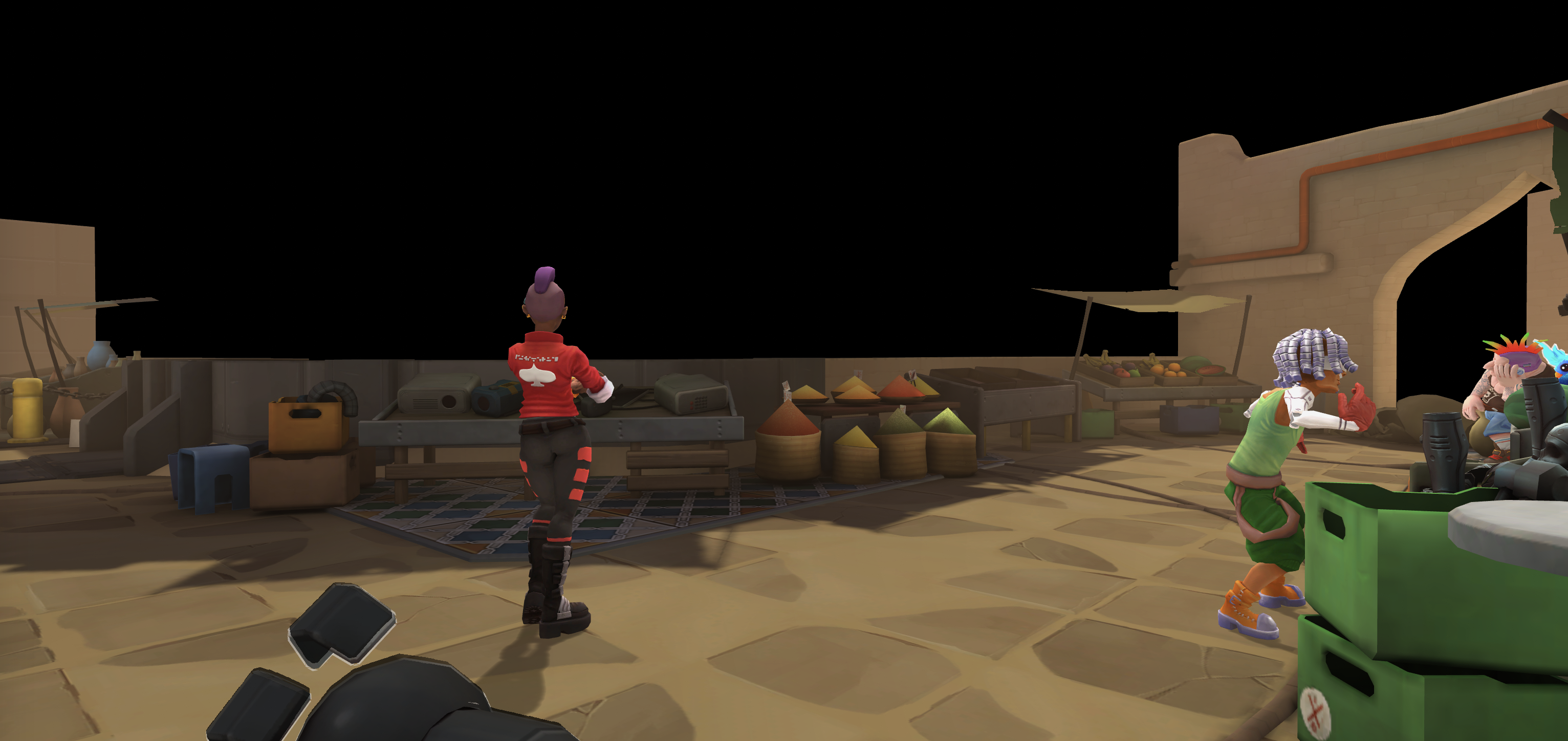
(Left) The Market demo scene with a blended fresnel darkening the edges of each shape.
(Right) A debug view of the same scene showing the affected areas and blended fresnel attenuation.
There’s one more issue to resolve - if the camera is ever inside of an imprint, then the imprinted object still appears dark. As it turns out, this happens for two reasons:
- Unsurprisingly, the
Imprint/Makeshader culls back-facing geometry and the primitive meshes just have single-sided front-facing geometry. This can be fixed by settingCull Offin the shader. - The fresnel calculating uses the dot product of the eye normal and vertex normal. When the camera is inside the geometry, these become colinear whereas they’re normally opposing. When the vectors are opposed, then their dot product approaches -1 which means the fresnel becomes
1 - pow(1 - 1)or simply 1. Colinear vectors have a dot product of 1 which means the fresnel becomes1 - pow(1 + 1)or simply -1. Thankfully we can treat opposing and colinear vectors the same if we subtract the absolute dot product.
(Left) The Market demo scene from inside an imprint missing its highlight.
(Right) The same scene with the inside highlight fixed.
1
2
3
4
5
6
7
8
9
10
11
12
13
14
15
16
17
18
19
20
21
22
23
24
25
26
27
28
29
30
31
32
33
34
Shader "Imprint/Make" {
    HLSLINCLUDE
        // The rest of HLSLINCLUDE is the same as above

        Varyings Vert (Attributes input) {
            Varyings output = (Varyings)0;

            float4 positionWS = mul(unity_ObjectToWorld, input.positionOS);
            output.positionCS = mul(unity_MatrixVP, positionWS);

            // Calculate fresnel
            // In this case the fresnel is inverted so that edges are darkened.
            // Taking the absolute value of the dotted normals also ensures that if the camera
            // is inside the geometry it will appear bright instead of dark.
            float3 eyeNormalWS = normalize(positionWS.xyz - _WorldSpaceCameraPos.xyz);
            half3 vertNormalWS = normalize(mul(unity_ObjectToWorld, input.normalOS));
            output.fresnel = 1. - pow(1. - abs(dot(eyeNormalWS, vertNormalWS)), 0.75);

            return output;
        }
    ENDHLSL

    Category {
        Tags { "IgnoreProjectors" = "True" }

        LOD 100
        Blend One One
        BlendOp Max
        Cull Off
        ZWrite Off

        // SubShader is same as above
    }
}
An In-Depth Look
Depending on the position of your camera and other objects in your scene, you may notice that objects which appear in front of imprints are also drawn bright even if they’re not themselves marked for imprinting. While this might be perfectly desirable for your situation, I preferred to keep foreground objects outside of the imprint dark. I think this is less visually jarring since it keeps your eye focused on the imprinted area not whatever happens to be in front of it. Thankfully we can sample the _CameraDepthTexture drawn when rendering the scene normally to compare the scene depth versus the imprint depth to decide if the pixel should be affected by an imprint or not. If the scene depth is less than the imprint depth (i.e. there’s an object between the camera and an imprint), then we can leave it dark.
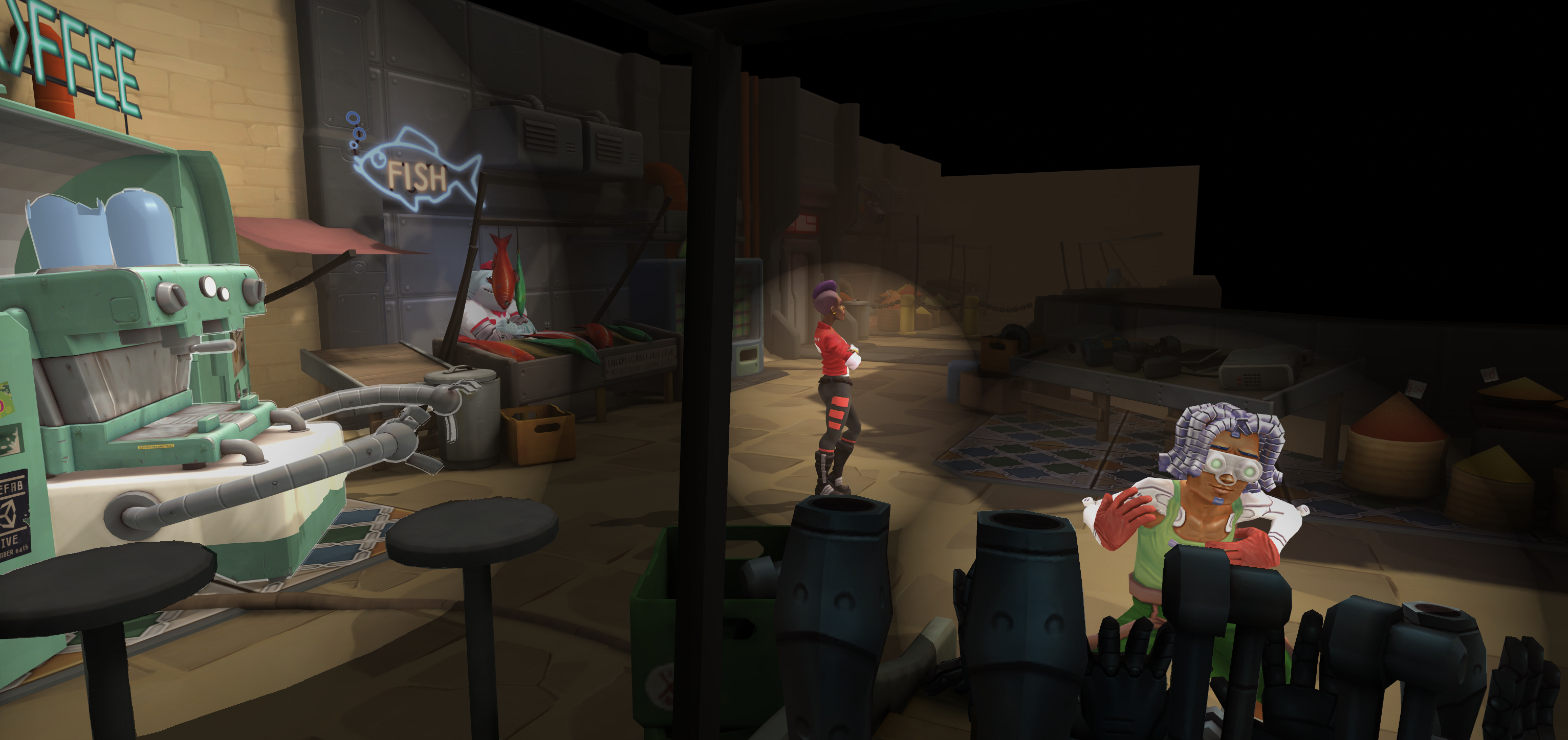
(Left) The Market demo scene with foreground objects darkened.
(Right) A debug view of the same scene showing the foreground objects in black.
For efficiency reasons, cameras do not draw to a depth texture by default, but you can configure them to do so. I’ve updated the ImprintRenderer to change the camera depth texture mode if necessary as follows:
1
2
3
4
5
6
7
8
9
10
11
        public override void Render(PostProcessRenderContext context)
        {
            // Ensure that the camera is setup to manage a depth texture so that it can be used by the
            // Imprint/Make shader.
            if ((context.camera.depthTextureMode & DepthTextureMode.Depth) != DepthTextureMode.Depth)
            {
                context.camera.depthTextureMode |= DepthTextureMode.Depth;
            }

            // The rest of Render is the same as above
        }
We’ll need to update the Imprint/Make shader to sample from the depth texture as well:
1
2
3
4
5
6
7
8
9
10
11
12
13
14
15
16
17
18
19
20
21
22
23
24
25
26
27
28
29
30
31
32
33
34
35
36
37
38
39
40
41
42
43
44
45
46
47
48
49
50
51
52
53
54
55
56
57
58
59
60
61
62
63
64
65
66
    HLSLINCLUDE
        #include "Packages/com.unity.postprocessing/PostProcessing/Shaders/StdLib.hlsl"

        TEXTURE2D_SAMPLER2D(_CameraDepthTexture, sampler_CameraDepthTexture);
        float4x4 unity_MatrixV;

        struct Attributes {
            float4 positionOS : POSITION;
            float3 normalOS : NORMAL;
        };

        struct Varyings {
            float4 positionCS : SV_POSITION;

            float4 positionSS_depth_fresnel : TEXCOORD0;
            // xy = positionSS, z = depth, w = fresnel
        };

        #if defined(UNITY_REVERSED_Z)
            #define COMPARE_DEPTH(a, b) step(b, a)
        #else
            #define COMPARE_DEPTH(a, b) step(a, b)
        #endif

        Varyings Vert (Attributes input) {
            Varyings output = (Varyings)0;

            float4 positionWS = mul(unity_ObjectToWorld, input.positionOS);
            output.positionCS = mul(unity_MatrixVP, positionWS);

            // Calculate positionSS, this is equivalent to ComputeScreenPos
            output.positionSS_depth_fresnel.xy =
                (output.positionCS.xy / output.positionCS.w) * 0.5 + 0.5;
#if UNITY_UV_STARTS_AT_TOP
            output.positionSS_depth_fresnel.xy *= float2(1.0, -1.0);
            output.positionSS_depth_fresnel.xy += float2(0.0, 1.0);
#endif

            // Calculate depth, this is equivalent to ComputeEyeDepth
            output.positionSS_depth_fresnel.z = -mul(unity_MatrixV, positionWS).z;

            // Calculate fresnel
            // In this case the fresnel is inverted so that edges are darkened.
            // Taking the absolute value of the dotted normals also ensures that
            // if the camera is inside the geometry it will appear bright instead of dark.
            float3 eyeNormalWS = normalize(positionWS.xyz - _WorldSpaceCameraPos.xyz);
            half3 vertNormalWS = normalize(mul(unity_ObjectToWorld, input.normalOS));
            output.positionSS_depth_fresnel.w =
                1. - pow(1. - abs(dot(eyeNormalWS, vertNormalWS)), 0.75);

            return output;
        }

        half4 Frag (Varyings input) : SV_Target {
            half packedDepth = SAMPLE_DEPTH_TEXTURE(
                _CameraDepthTexture,
                sampler_CameraDepthTexture,
                input.positionSS_depth_fresnel.xy);
            float sceneDepth = LinearEyeDepth(packedDepth);

            return COMPARE_DEPTH(sceneDepth, input.positionSS_depth_fresnel.z)
                * input.positionSS_depth_fresnel.w;
        }
    ENDHLSL

    // The rest of the shader is unchanged
Conclusion
Imprints now have a soft edge, blend correctly when overlapping, and don’t cause foreground objects outside of the imprint to appear bright. There’s potentially still room for improvement beyond the scope of this post - specifically using instancing to draw imprints more efficiently which will require changes to both the ImprintRenderer and Imprint/Make shader. I decided not to pursue it because there was already enough content to discuss and my specific use case didn’t involve more than a handful of objects to highlight. I’m pretty happy with the result but let me know if you see other areas for improvement.